For critical applications that demand highly customized modules, system architects often face the challenge of high costs due to small batch production. However, we have developed an innovative and cost-effective approach to transform commodity components into high-reliability modules capable of withstanding frequent and large temperature excursions.
| Package Variant | Description |
|---|---|
| Config. 1 | Micron MT40A512M16LY-062E IT:E (COTS with SAC302 Balls) |
| Config. 2 | Config. 1 Re-balled with Eutectic SN63/Pb37 balls |
| Config. 3 | Config. 1 Repackaged as Overmolded 0.8mm Pitch Interposer with Eutectic Sn/Pb37 Balls |
The experiment involved subjecting the different module configurations to thermal cycling tests. The results clearly showed the superiority of the repackaged module (configuration 3), which exhibited a 2.5-fold improvement in thermal cycling survivability compared to the commercial off-the-shelf configuration. The failures in the non-overmolded modules (configurations 1 and 2) were mainly attributed to solder ball failures near the corners of the die. However, with the repackaged module, failures were largely restricted to the external solder balls connecting the component to the test board, while the solder balls between the original device and the interposer remained intact.
Watch as engineer Prashant Joshi takes you through the details of the study. A transcript is available below the video.
(Tom)
ISI was established in 1987 and became part of Molex in 2016. During this time, ISI has been providing custom microelectronics modules for the aerospace, industrial, medical, as well as other harsh environment applications.
Our main facility in Camarillo, California contains our engineering, manufacturing, program management, and customer service teams. We truly are your one-stop shop for microelectronics modules. We’re an ITAR-certified facility, as well as ISO and IPC certified.
ISI has broad manufacturing capabilities that you can leverage to ruggedize components for harsh environment applications. Specifically, we have SMT lines, a clean room with both wire bonding and flip-chip attachment capabilities, BGA re-balling capabilities, as well as electronic over-molding.
We’ve utilized all these capabilities to conduct an experiment on commercial off-the-shelf memory devices, and the experiment has proven that we can extend the solder joint reliability of these devices for harsh environment applications, including multiple thermal cycles.
To tell you more about that experiment, I’m going to hand it off to my colleague and engineering manager, Prashant Joshi. Prashant?
(Prashant)
Hello, my name is Prashant Joshi, and I’ll walk you through the technical portion of the presentation. ISI is a custom solutions provider specializing in miniaturization, modularization, and ruggedization. We have surface mount die-level packaging and interconnect capabilities, which we mix and match to create custom solutions for customers. Our typical high-reliability solutions for Mil/Aero customers are re-balling devices from lead-free to tin/led, unmolded interposers, and molded or over-molded BGA-type interposers.
For this study, we decided to compare these three different techniques using thermal cycling performance. Since DDR memory is a popular component, and we processed several ruggedized designs, a Micron DDR4 device was chosen for this comparison study.
Here’s the Micron device—DDR4 device. It’s 13.5mm by 7.5mm, 96 balls. The balls are SAC 302. It’s a low-profile device.
Here are more details of the device. These are the ball assignments, and if you zoom in, you can see the die inside. Here’s an X-ray image and, once you zoom in, you can see the die inside the package. These are all the different wire bonds. Here’s the edge of the die. The die goes from the third ball from the top to the third ball from the bottom, approximately, and then the second ball from the left to the second ball from the right. The die is smaller than the overall package.
We chose three different configurations. Here’s the first one. This is a COTS configuration, so as manufactured by Micron with SAC 302 balls.
For the second configuration, we re-balled the Micron device with eutectic tin/lead solder balls. For more details about our re-balling process, please visit our website and you can get your question answered.
For the third configuration, we chose a ruggedized Micron device. The Micron device is in here. It was surface-mounted on an interposer PCB, over-molded, and we balled the bottom side with eutectic tin/lead solder balls.
The overall molded package is slightly larger than the actual Micron device. The goal was to be able to mount the assembly on a footprint that was designed for the Micron device, so just slightly larger. To understand ISI’s ruggedization process, please visit our website and you can look up “ruggedized microelectronic modules.”
For actual testing, we designed a small interposer test PCB. We mounted stacking connectors along the top and bottom edges. On the bottom side, you have the device under test. We chose a 30-piece sample size for each configuration for testing.
Configuration one, which is COTS lead-free, was assembled using a lead-free SAC305 water-soluble solder paste and a lead-free reflow profile.
For configurations two and three, which were eutectic tin/lead-based, used a eutectic tin/lead solder paste and a tin/lead reflow profile.
This slide shows the three different configurations for comparison. Here’s the thermal cycling profile. It goes from -40°C to +95°C, which is a typical requirement for ISI’s aerospace customers. At each temperature, we held it for 30 minutes and the target was 10,000 cycles.
These are all the different samples stacked together using those connectors, and the goal was to continuously monitor for opens and/or change in resistance.
We began conditioning, and we saw our first failure at about 750 cycles or hours. This was on configuration two, which is the eutectic tin/lead re-balled devices. The failing location was identified as DQ13 (so DQ13 is out here—this is the second row) so it’s an internal ball.
We cross-sectioned and we were able to see a crack on the joint, so our cross-sectioning matched what the electrical test was telling us.
We continued conditioning, and here’s a cross-section of a part that failed at 1,200 cycles. Here’s a cross section through row one. Row one did not show us any cracking. All these balls look almost intact except for a few showing partial cracking, but nothing that would have meant an open.
Initially, when we saw the first failure, the assumption was, with thermal cycling and with warp and twist—maybe it’s the corner ball that had moved or there were excessive stresses on the corner balls resulting in those balls failing. But this is not what the cross-section showed.
This is the second row. As we at this, you can see significantly wider cracks on some of these balls but the end solder balls don’t have any cracking. And, as you go towards the center—those look okay too. You have partial cracks. But these are the balls—the ones that are right under the die edge—seem to exhibit excessive cracking.
Once we got to the third row…these are zoomed-in views of these three solder balls. These are right under the die edge. As you can see, these are fully cracked. So A3 and T3 look good but it’s the balls that are right under the die edge that are cracking.
This indicates that maybe there is a correlation between the die…the CTE of the die with respect to…CTE of the die with respect to the package, and the stresses that are being generated on the solder balls due to…are because of the die movement and not the overall package.
The next two slides show parts…a part that failed at 900 cycles. This cross-section through row three. Again, same thing—same failure. We saw excessive cracking or failures right under the die edge.
More cross sections, same thing.
As we…after looking at all the failure modes…we looked at the points…at the balls that failed, and these are the ones shown here. The red is the die location—die size. And as you can see that the failing balls do coincide to line up—with the die edges.
So, as I said earlier CTE differences between the die and substrate might be causing the die…causing the Micron device to warp and stress those solder joints.
We continued conditioning and the next failure to show up was the COTS device with SAC302 solder balls. Here’s a part that failed at 1,500 cycles, which is almost 2x the performance of tin/lead.
This sample failed at 2,800 cycles.
As you can see again, the failing balls do line up with the die edge. The end balls look pretty decent.
More cross sections.
This assembly failed at 2,200 cycles…more zoomed-in views of the solder balls. Here, C8 is completely cracked—that would be C8. And this is P2, which would be the third ball here.
So, similar to the tin/lead configuration, these failures did line up with die edges.
We continued conditioning and finally we got to failures on the ruggedized design. So, the first failure on the ruggedized design was at 6,000 cycles. That’s about 8x the tin/lead, and 4x…four times the SAC302 failure.
So, we sectioned…here the cross-sections only show you external solder balls. The internal solder balls or the device solder balls are overmolded, and just to be able to show you details of the external solder balls we did not show the internal solder balls in cross sections.
Here you can see some cracking along the external solder balls. We…here’s a cross-section through row 2. This seems to have more cracking. This seems to be fully cracked. That seems to be cracked. Minor cracking all the way into…towards the center of the part. So this would be the center of the part.
Section through row 3. Again, more cracking, even closer to the center of the part. We didn’t really observe any patterns in these failures, and after completion of about 7,500 cycles only 8 of the 30 pieces had failed. Here’s the distribution of the three different configurations.
This is eutectic tin/lead, tight distribution. Most of them failed within, let’s say, 1,500 cycles.
SAC302 in blue. They’re more spread out, and failed at under…around 3,000 cycles.
And this is the ruggedized design.
For summary, the die substrate CTE differences play a significant role in solder ball joint failures under thermal cycling. Ruggedization redistributes CTE related stresses across device solder joints while allowing reworkability, unlike underfill.
So, if you took a Micron device, put it down directly on the PCB and underfilled…underfilled the solder joint, yea you would get good performance. But if you had to rework, it would be a painful process.
With this ruggedized module, you just put it down—there is no underfill. So, if you have a failure, you can just remove the ruggedized device and replace it with a new one.
The interposer substrate decouples interposer solder balls from the die.
Ruggedization can significantly improve performance, 8x compared to tin/lead, and 4x compared to lead-free COTS devices—and this is beneficial for high-reliability applications with large and frequent thermal cycles.
Ruggedization can be achieved without significantly increasing the body size and while using the same PCB footprint as the original design.
So, this is a…this is nice because you can just replace the Micron device with a ruggedized design.
And commercial devices…so anything that has a silicon die, a substrate, overmolding, and solder balls—so, any recipe that includes all of these—could probably see a benefit with ruggedization.
For future plans, we are looking at some modifications…or moving to a PCB with a wider pitch, a larger solder ball. We believe that those might actually improve performance.
And we’re also looking at developing simulation capabilities to predict performance with die, substrate sizes—even temperature extremes and other variables.
Thank you for listening. If you have any questions, please contact ISI and we can set up a conference call with you to discuss additional details as required, thank you!
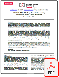
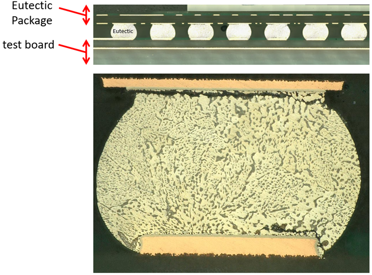
Configuration 1: COTS Micron component (SAC302 solder balls) and Configuration 2: Micron component with SAC302 balls replaced with eutectic tin/lead balls
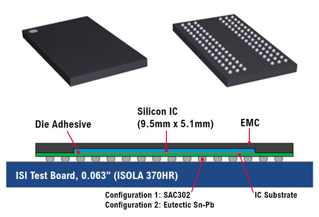
Configuration 3: The COTS Micron part repackaged on an interposer having the same 0.8 mm pitch, eutectic tin/lead balls, and overmolded
This study highlights the significant benefits of our simple repackaging approach, resulting in a substantial improvement in thermal cycling survivability. The technique can be applied to various commercial BGA type devices, offering a low-cost alternative to custom-designed bare die package assemblies. Based on these findings, further enhancements can be achieved by redistributing frequently failing nets away from high-stress solder balls, thus extending the lifespan of the repackaged parts and reducing maintenance costs in systems exposed to extreme temperature excursions.
Choose our cost-effective ruggedization solution and ensure the reliability and durability of your critical applications. Contact us today to learn more about transforming commodity components into ruggedized, high-reliability components.
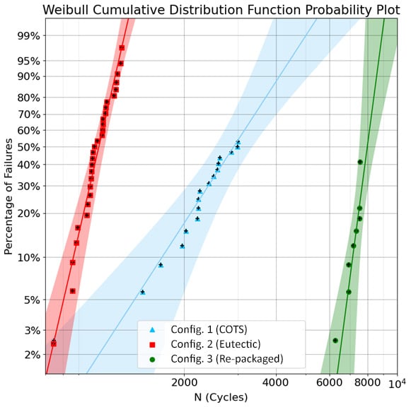
Pictured (above): The measured cumulative failures for each of our three component populations as a function of the number of thermal cycles is plotted (above left). The Configuration 1 COTS micron component (blue), Configuration 2 eutectic re-balled Micron component (red), and the Configuration 3 repackaged component (green). A two parameter Weibull continuous distribution function is fit to each component’s data. The shaded areas represent the 95% confidence band for each data set.
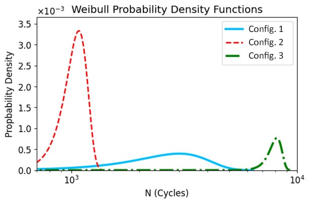
Also plotted (above right) are the Weibull probability density functions for each of the populations based on the fitted parameters.
Pictured (left):
A typical eutectic solder ball failure in the Configuration 2 component. These failures are most prevalent in balls located near the corners of the of the die. The fractures are located on the lower inside and upper outside edge of the solder ball. This indicates that the highest stresses occurred during the contracted stage (cool) of the thermal cycle. The Configuration 1 component showed similar failures.